DIY Arduino Heat Bed for 3D Printer
Standalone Arduino-controlled heat bed system for upgrading obsolete 3D printers. Features temperature control, safety monitoring, and modular design for retrofitting older printer models without built-in heated beds.
As an Amazon Associate, I earn from qualifying purchases. The linked products are the ones I suggest or that I personally used on my project, so feel free to find parts that define your own project.
Overview
I bought a Sindoh DP201 3D printer back in 2017 which didn’t come with heated bed. I’ve been frustrated by the warping issue of my prints for 2 years so I decided to add my own heat bed. I made irreversible changes to the printer metal plate to accommodate the heat bed. So don’t start breaking your printer before you know exactly what you are doing. Note that Sindoh’s later products do come with heat bed, like the 3DWOX 1. Most 3D printers in the market now(2021) come with heat beds. So this guide is only useful for DIYers who wants to upgrade their older 3D printers.
Necessary Parts
- Since this project requires minimal processing power, any Arduino is up to the task.
2. Heat Bed
- Measure your build plate size before purchase.
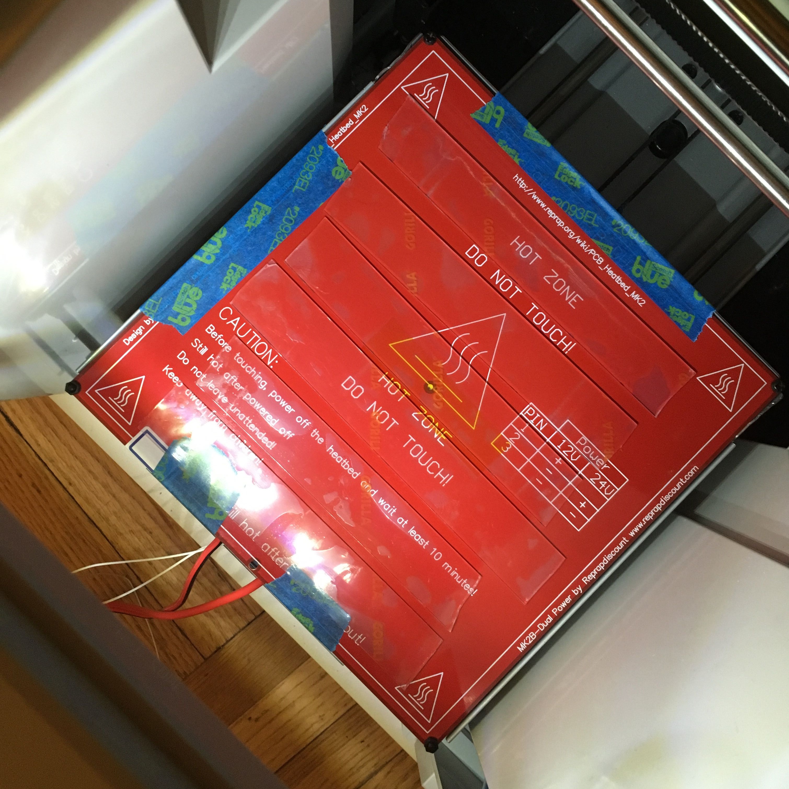
- This is what I got: MK2B Heated Bed with Soldered NTC 3950 Thermistor. It comes with a thermistor soldered.
- You might want to get a different build surface of your choice, could be glass or magnetic(suggested in the optional parts section)
3. Thermistor
- You might NOT need to buy an extra thermistor if it’s already included in the heat bed, like mine did(see above).
- You DO need a 100K Ohm resistor to allow the Arduino to get temperature readings.
4. Light Sensor
- A light sensor is perfect for detecting if the 3D printer is printing. I changed my 3D printer’s setting to turn on the lamp only when it’s printing. You can program the Arduino to turn on the heat bed when the light intensity reading is above some value.
5. Display
- You might use it to display sensor readings such as temperature and light intensity. But it’s not absolutely required.
- I used this: I2C Serial OLED LED Module 128X64
- The MOSFET control requires a heat sink and an activation signal voltage of 5V
- There are some MOSFET controls on the market that don’t work with Arduino because the Arduino digital PWM output is only 5V. This, for example, will not work with Arduino: it needs at least 6.4V signal voltage to activate this MOSFET.
- This is what I got: UEETEK 3D Printer Heating Controller MOSFET. Highly recommend.
7. 12V DC Switching Power Supply
8. Electrical Cord for the power supply
Optional Parts
- If you don’t want to put too much “pressure” on the Arduino built-in regulator, use an external voltage regulator like I did.
- You can also use your voltage regulator as a switch.
2. A New Flexible Magnetic Build Surface
- I tested this magnetic surface on a few Ender 3D printers, and they worked great!
3. Buttons
- If you want to control your heat bed with a button, do so.
- I have a 5 Way Navigation Button Module on board in case I want to set a specific time for the heat bed. It turns out that the light sensor does all the work for me.
- This is one of my favorite 5-way button modules of all time, perfect for DIY Arduino LCD/OLED Controller projects. See my Radio Controller project for a Octopod Spider Robot.
- I have it included in my project but I didn’t use it at all.
- Use this module if you want a timer system for your heat bed.
Gallery
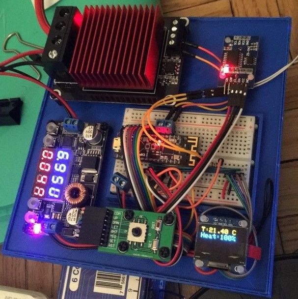
↓ The finished control board with project enclosure.
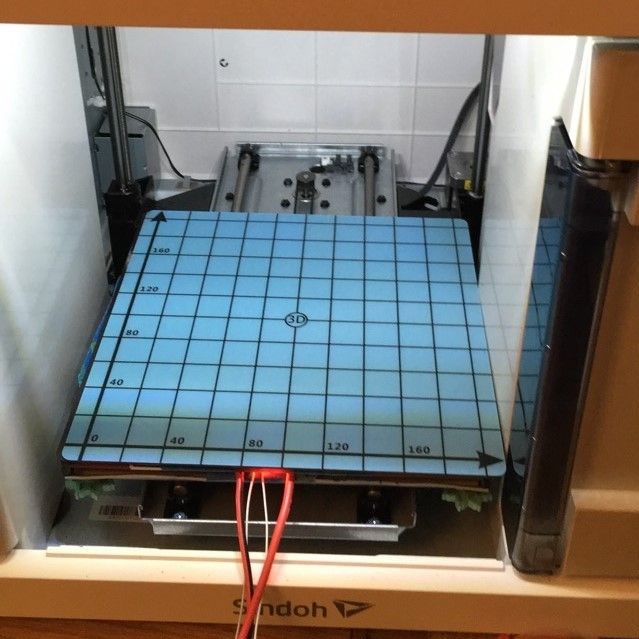
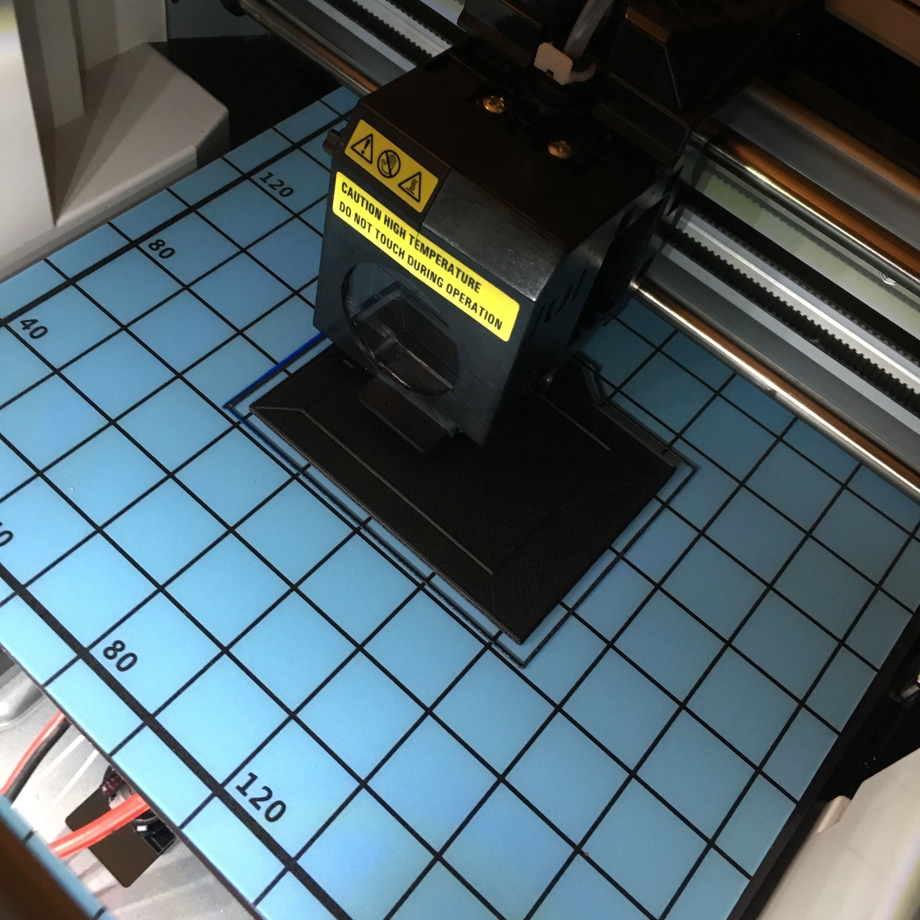
↓ Fix the heat bed onto the built plate.
↓ Finish up the build plate with the optional magnetic build surface.
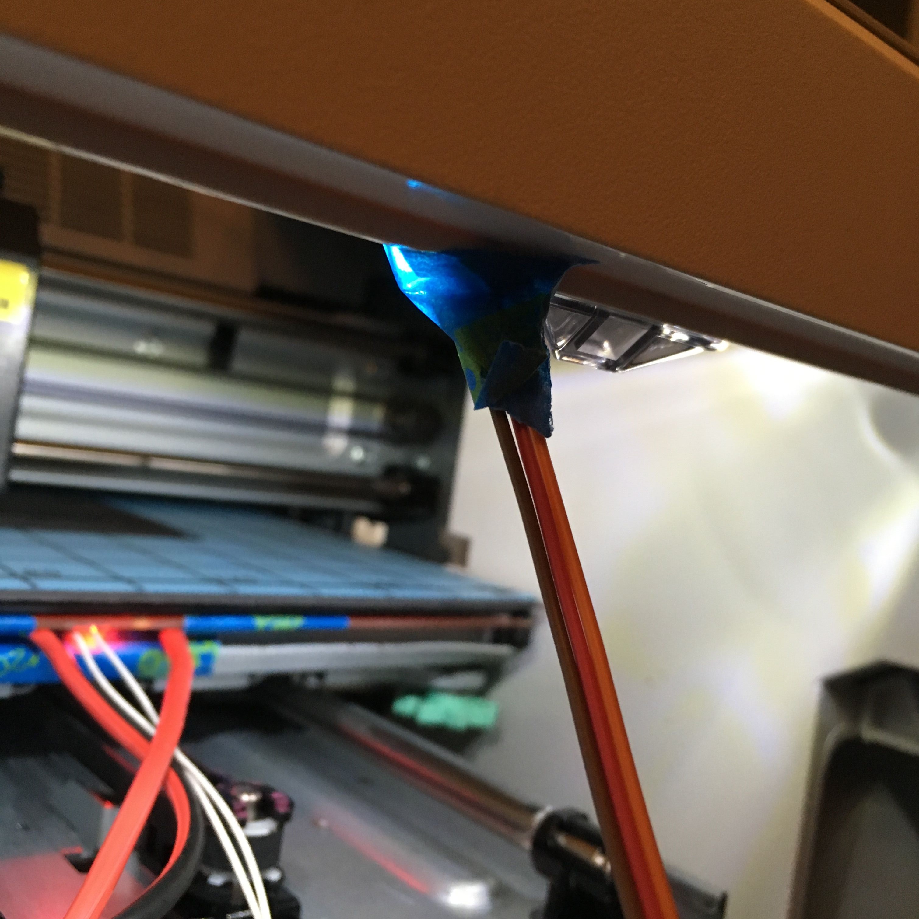
↓ Install your light sensor right next to the printer lamp for automated print detection.
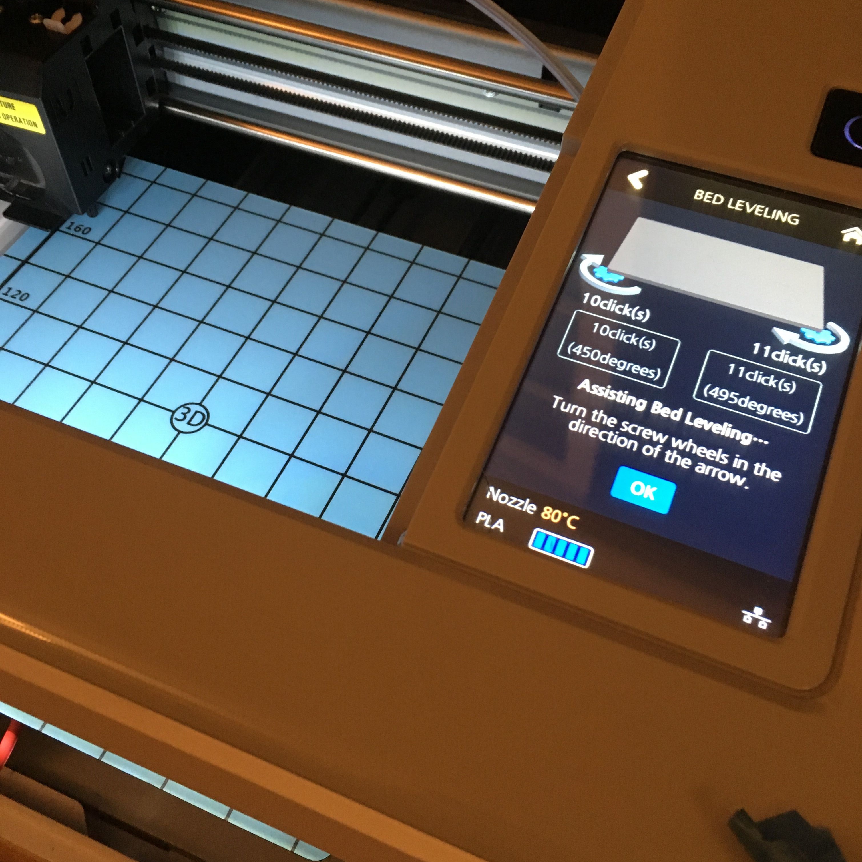
↓ Remember to change your Z-offset and level your bed.
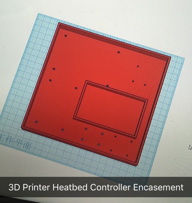
↓ Print your own project enclosure to hold all components together. Here is the Link to my 3D design
↓ Now you can print without warping issue.
Code
// in case someone needs the code
#include <Adafruit_GFX.h>
#include <gfxfont.h>

#define NUMSAMPLES 5
#define mosPin 3
#define lightPin 3
#define thermistorPin 7

#define minTemp 60
#define maxTemp 80

#include <SPI.h>
#include <Wire.h>
#include <Adafruit_GFX.h>
#include <Adafruit_SSD1306.h>

#define OLED_RESET 4
Adafruit_SSD1306 display(OLED_RESET);

#define NUMFLAKES 10
#define XPOS 0
#define YPOS 1
#define DELTAY 2


#define LOGO16_GLCD_HEIGHT 16
#define LOGO16_GLCD_WIDTH  16
static const unsigned char PROGMEM logo16_glcd_bmp[] =
{ B00000000, B11000000,
  B00000001, B11000000,
  B00000001, B11000000,
  B00000011, B11100000,
  B11110011, B11100000,
  B11111110, B11111000,
  B01111110, B11111111,
  B00110011, B10011111,
  B00011111, B11111100,
  B00001101, B01110000,
  B00011011, B10100000,
  B00111111, B11100000,
  B00111111, B11110000,
  B01111100, B11110000,
  B01110000, B01110000,
  B00000000, B00110000 };

#if (SSD1306_LCDHEIGHT != 64)
#error("Height incorrect, please fix Adafruit_SSD1306.h!");
#endif


int samples[NUMSAMPLES];

int Vo;
float R1 = 100000;
float logR2, R2, T, Tc, Tf;
float c1 = 0.7203283552e-3, c2 = 2.171656865e-4, c3 = 0.8706070062e-7;

void setup() {
Serial.begin(9600);
pinMode(mosPin, OUTPUT);
// by default, we'll generate the high voltage from the 3.3v line internally! (neat!)
  display.begin(SSD1306_SWITCHCAPVCC, 0x3C);  // initialize with the I2C addr 0x3D (for the 128x64)
  // init done

  // Show image buffer on the display hardware.
  // Since the buffer is intialized with an Adafruit splashscreen
  // internally, this will display the splashscreen.
  display.display();
  delay(1000);

  // Clear the buffer.
  display.clearDisplay();
}

void tempRead(){
  uint8_t i;
  float average;

  for (i=0; i< NUMSAMPLES; i++) {
    samples[i] = analogRead(thermistorPin);
    R2 = R1 * (1023.0 / (float)samples[i] - 1.0);
    logR2 = log(R2);
    T = (1.0 / (c1 + c2*logR2 + c3*logR2*logR2*logR2));
    samples[i] = T - 273.15;
    delay(10);
  }
  average = 0;
  for (i=0; i< NUMSAMPLES; i++) {
     average += samples[i];
  }
  average /= NUMSAMPLES;
  Tc = average;
//  Serial.print(Tc);
//  Serial.print(" C ");

  display.setTextSize(2);
  display.setTextColor(WHITE);
  display.setCursor(0,0);
  display.print("T:");
  display.print(Tc);
  display.println(" C");
}

void turnOnHeat(){
  analogWrite(mosPin, 255);
}

void turnOffHeat(){
  analogWrite(mosPin, 0);
}

void turnHeatNum(int num){
  analogWrite(mosPin,int(num));
}

void mosfetControl(bool on){
  display.print("Heat:");
  if (Tc < minTemp && on){
    turnOnHeat();
    display.println("100%");
  }
  else if (!on || Tc > maxTemp ){
    turnOffHeat();
    display.println("0%");
  }
  else {
    int num;
    num = int(-(255/(maxTemp-minTemp))*(Tc-minTemp)+255);
    Serial.println(num);
    turnHeatNum(num);
    display.print(int(num*100/255));
    display.println("%");
  }
}

bool isLightOn(){
  float sensitivity = 700;
  float lightRead;
  lightRead = analogRead(lightPin);
  display.print("L:");
  display.print(lightRead/1023*100);
  display.println("%");
  if (lightRead > sensitivity){
    return true;
  }
  return false;
}

void loop() {
  tempRead();
  if (isLightOn()){
    mosfetControl(1);
  }
  else {
    mosfetControl(0);
  }

  display.display();
  delay(500);
  display.clearDisplay();
}
Discover more...
Water Pump - Relay Module
Audio Jack Reader - Signal Processing